D-CODE 30
Made with microStudio
DESCRIPTION:
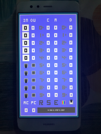
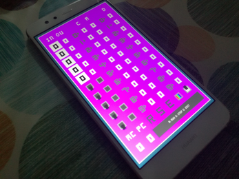
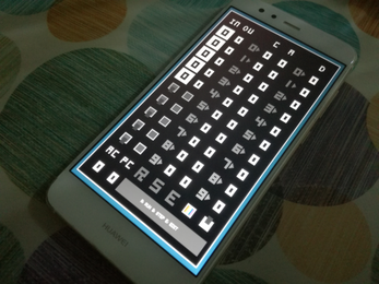
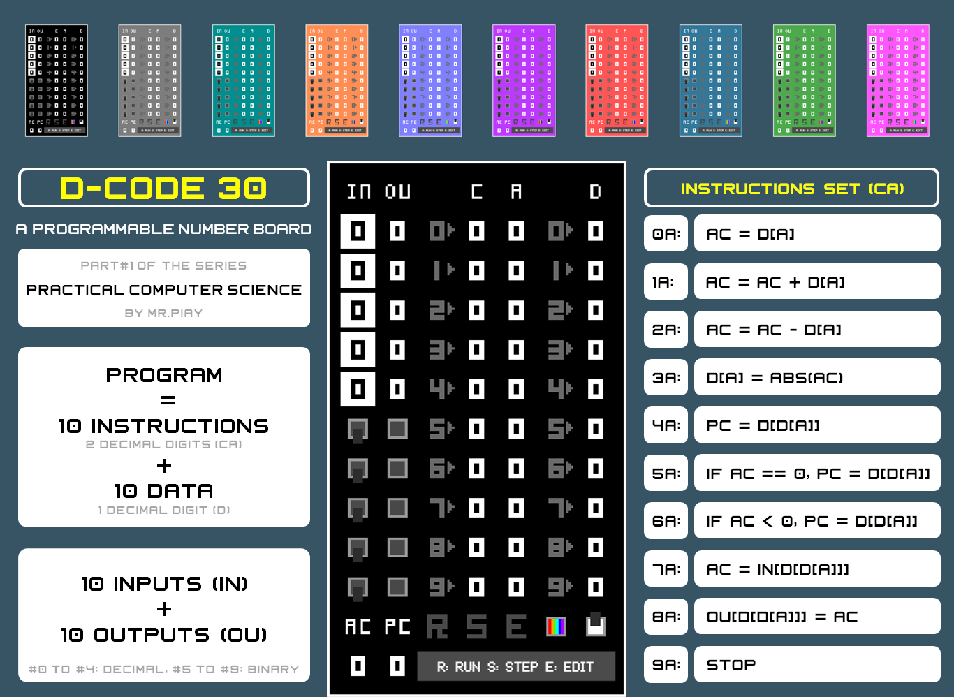
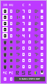
D-CODE 30 is a learning & training tool included in the "Practical Computer Science" series created by Mr. Piay, conceived to help students & enthusiasts get started with computer architecture & machine code programming.
The device can run programs consisting, at the most, of 10 instructions (with 2 decimal digits each) and 10 data (with 1 decimal digit each) and is operated by just clicking or tapping on the screen (100% mobile friendly).
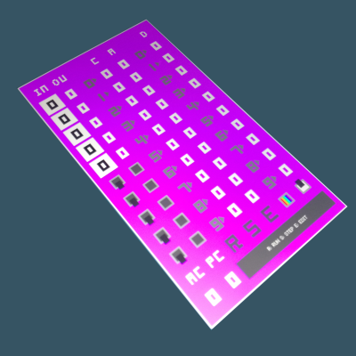
The instructions set allows 10 single operations. The leftmost digit (C) of the instruction indicates the type or code of operation, and the rightmost digit (A) indicates the address of the data (D), or the position where it will be read from or written to, which depends on the addressing mode used:
- Direct D[A]: A is the address of the data.
- Indirect D[D[A]]: A is the address of the address of the data.
OPERATION:
- Click on E to start/finish writing the program. Values are entered by clicking successively on the corresponding place.
- Click on R to run/stop the program.
- Click on S to select/exit the Step mode and then click on R to go through the fetch-decode-execute operation cycle.
In addition to the 10 positions for instructions and data, the device has an accumulator (AC) and a program counter (PC). The accumulator can hold both positive and negative values.
The device has 10 inputs (IN) and 10 outputs (OU). #0 to #4 are decimal and #5 to #9 are binary (switch button and led type). Binary outputs will be ON if the vale of the accumulator is greater than 0.
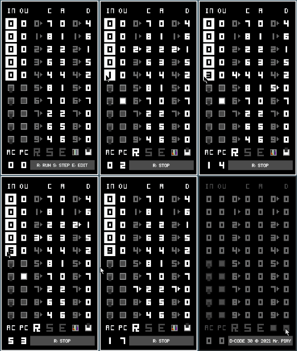
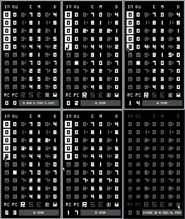
Example: how to write a program to set the value of digital output #9 to the value of digital input #9.
PROGRAM CARDS
You can share yours in the community section!

CARD #0
THE SIMPLEST GAME
Just switch on the device and click on R to let the program counter cycle the 10 positions for instructions.
Click on R to try to stop the program counter at position #5.

CARD #1
SET OUTPUT #N TO THE VALUE OF INPUT #N
Change the inputs while the program is running and see how the outputs change accordingly.
CARD #2
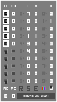
SET ALL THE OUTPUTS TO THE VALUE OF INPUT #9
CARD #3
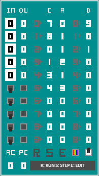
INCREMENT OUTPUT #4 WHEN INPUT #5 CHANGES
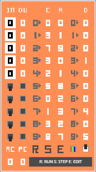
CARD #4
MULTIPLICATION
D[2] = D[0] x D[1] (D[0] = 2 and D[1] = 4)
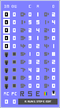
CARD #5
INTEGER DIVISION
[2] = D[0] / D[1] (D[0] = 9, D[1] = 2, D[0] = REMAINDER)
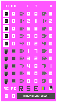
CARD #6
LOGICAL NOT
OUTPUT #9 = NOT INPUT #9
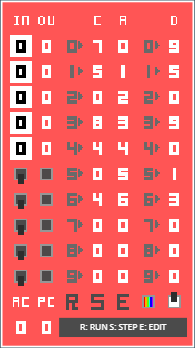
CARD #7
LOGICAL AND
OUTPUT #9 = INPUT #8 AND INPUT #9

CARD #8
LOGICAL OR
OUTPUT #9 = INPUT #8 OR INPUT #9

CARD #9
D-LATCH
IF INPUT #8 == 1 THEN OUTPUT #9 = INPUT #9
CARD #10
ADJUSTABLE BLINKING LED
OUTPUT #6 BLINKS WITH FREQUENCY CONTROLLED BY INPUT #4
(THE HIGHER THE INPUT, THE LOWER THE FREQUENCY)
| Status | Released |
| Category | Tool |
| Platforms | HTML5, Android |
| Author | mrpiay |
| Genre | Educational, Simulation |
| Tags | assembly, coding, computer, cpu, microstudio, programming |
Download
Development log
- BugfixJul 23, 2021
